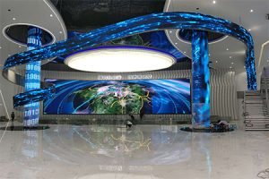
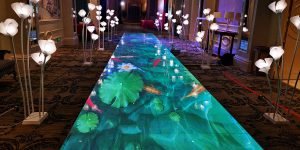
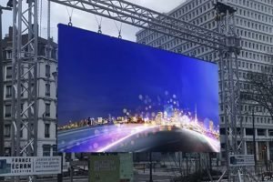
In large shopping centers, hospitals, railway stations, airports and other public places, the most eye-catching is always the LED advertising screen. Its existence is to make the monotonous scene become handsome, guide, help, show wonderful pictures and understand new things. It is not only convenient for your life, but also makes your life better.
What is led electronic screen?
LED electronic screen is a liquid crystal display composed of small LED module panel.
LED, short for LED. The diode used to control the display mode of semiconductor light-emitting diode is composed of gallium (GA), arsenic (as), phosphorus (P), nitrogen (n) and indium (in). When electrons and holes are combined, they can emit visible light for making light-emitting diode. It is indicated by indicator light or configuration letter or number in circuit and instrument. Gallium arsenophosphate diode emits red light, gallium phosphate diode emits green light, silicon carbide diode emits yellow light, and InGaN diode emits blue light.
How to make LED electronic screen?
1. Frame part (special aluminum profile, corner, light steel keel, back baffle), 2. Display part (module, screw, magnet, power line), 3. Control part (sending card, receiving card, network cable, etc.), 4. Power part (power supply).
Process steps:
1. To determine the size of the unit board, it must be very accurate.
Calculate the net size of the height and width of the unit board on the LED electronic screen.
3. Subtract 4mm from the calculated net size (if the LED electronic screen exceeds 3M, subtract 5mm)
4. The corner and cut outline should be arranged with self tapping joint, and the neat groceries should face down.
5. Please place the unit board according to the direction. Where there is a pin, please face the height of the outline.
6. Load the magnet column on the army board and broadcast the floppy disk to the groove of the column base.
7. Please carefully measure the required length of light steel keel, and then put it on the magnet.
8. It is recommended to use it as self tapping and frame joint.
9. Lift the unit board with the cable to build the bridge, and the cable is not allowed to skew.
10. Secure the power supply in place in the configuration file.
11. Connect the power cord.
12. Place the controller card on the input of the unit board.
13. The pins on the controller card are distinguished in order. Jk1. JK2. Or JP1. JP2. With the same position, you need to connect the unit board to the top of the arrow at the input end of the unit board.
14. Unit board and choke joint: generally, there is a small white letter a around the controller pin, and there is also such a letter at the input end of unit board. But the two A’s parallel to the row line are correct.
15. After finishing the above work, clean up the sundries on the screen.
16. If the digital cable is well done, carry out the power test.
17. The staggered line and the two straight lines that don’t want to intersect are the same sentence. The use of parallel is still staggered.
18. After the above work, the rest is adjustment. But the LED electronic screen must have power capacity adjustment.
How is led electronic display made