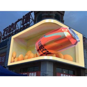
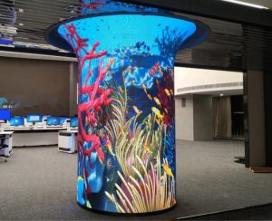
The failure of full-color LED electronic screen is usually caused by improper installation, so the installation of full-color LED electronic screen must strictly follow the procedures. Especially the first installation, can reduce the occurrence of errors, powerful large screen installation enterprises always have high requirements to install their own products. Next, please check the wiring method in the display installation of the powerful large screen installation company.
1. Confirm the power supply voltage
Find the DC positive and negative connection switch power supply, connect the 220 V power line to the switch power supply (make sure the connection is correct, and then connect to the AC or NL power supply), and then connect the power supply. The indicator light on the power supply lights up, and then use a multimeter to measure the voltage between V and V to determine the voltage between 4.8V and 5.1V. There is a handle beside which the voltage can be adjusted with a cross screwdriver. In order to reduce the brightness requirement of the screen to 4.5V, it can be adjusted to extend the service life of the screen. After confirming that there is no problem with the voltage, disconnect the power supply and continue to assemble other parts.
2. Turn off the power first
Connect V to red line, V to black line, control card and indicator unit board, and connect GND of control card and power supply to black line. The red line connects the 5V of the controller card and the VCC of the unit board. Each device motherboard has one power cord. When finished, verify that the connection is correct.
3. Connecting control and equipment boards
Connect with a good ribbon cable. Be careful of the direction and don’t object. Two 16 pin connectors of unit board, one is input, the other is output, and close to 74hc245 / 244 is input, connect the control card with input. Export input connected to the following cell boards:
4. RS232 data line
One of the good data cables is connected to the DB9 serial port of the computer, the other is connected to the controller card, the 5-pin (brown) of DB9 is connected to the GND of the controller card, and the 3-pin (brown white) of DB9 is connected to the rs232-rx of the controller card. If your PC does not have a serial port, you can go to the computer city and use the usb-rs232 serial port instead.
5. Recheck the connection
Yeah, the black line connects – V to GND. The red line connects V and VCC 5V.
6220v, open the downloaded software
Under normal conditions, the power indicator light is on, the controller card is on, and the LED electronic screen is marked. If not, check the connection. Or check for bug fixes. Set the parameters of the screen to transfer the annotation. Refer to the software instructions for details.
This is the specific steps of the installation and wiring of the powerful large screen installation program, which is to combine the strict training of the engineering department under the above steps with the excellent quality of the product itself, so as to create the success of the powerful LED electronic screen installation program.


